| Ligne 111 : | Ligne 111 : | ||
|Step_Title=Le Code | |Step_Title=Le Code | ||
|Step_Content=<code> | |Step_Content=<code> | ||
| − | ; #define data 2 | + | ;#define data 2 |
| + | ;#define clock 3 //D PWM | ||
| − | ; | + | ;/* |
| + | ; * CHILLER DISP Rev 0.0 | ||
| + | ; LED Display: ___ | ||
| + | ;; 6! 1 !2 | ||
| + | ;; ! ! | ||
| + | ;; --- | ||
| + | ;; ! 7 ! | ||
| + | ;; 5! !3 | ||
| + | ;; --- | ||
| + | ;; 8° 4 bits: 12345678 | ||
| + | ; Connectors: | ||
| + | ;; CON3 | ||
| + | ;; GND GND GND | ||
| + | ;;SW2 DATA | ||
| + | ; CON2 SW1 GND CON1 | ||
| + | ;;CLK +5V | ||
| − | ; | + | ; */ |
| − | |||
| − | |||
| − | |||
| − | |||
| − | |||
| − | |||
| + | ;void setup() | ||
| + | ;{ | ||
| + | ; pinMode(clock, OUTPUT); // make the clock pin an output | ||
| + | ; pinMode(data , OUTPUT); // make the data pin an output | ||
| + | ; } | ||
| − | + | ;void loop() { | |
| − | + | ; // put your main code here, to run repeatedly: | |
| − | |||
| − | |||
| − | |||
| − | |||
| − | |||
| − | |||
| − | |||
| − | |||
| − | |||
| − | |||
| − | |||
| − | |||
| − | |||
| − | |||
| − | |||
| − | |||
| − | |||
| − | |||
| − | + | ; shiftOut(data, clock, LSBFIRST, B00000000); // send this binary value to the shift register | |
| − | + | ; shiftOut(data, clock, LSBFIRST, B00000000); // send this binary value to the shift register | |
| + | ; shiftOut(data, clock, LSBFIRST, B00000000); // send this binary value to the shift register | ||
| + | ; shiftOut(data, clock, LSBFIRST, B00000000); // send this binary value to the shift register | ||
| + | ; delay(1000); | ||
| + | ; shiftOut(data, clock, LSBFIRST, B00000001); // send this binary value to the shift register | ||
| + | ; shiftOut(data, clock, LSBFIRST, B00000010); // send this binary value to the shift register | ||
| + | ; shiftOut(data, clock, LSBFIRST, B00000100); // send this binary value to the shift register | ||
| + | ; shiftOut(data, clock, LSBFIRST, B00001000); // send this binary value to the shift register | ||
| + | ; delay(1000); | ||
| + | ; shiftOut(data, clock, LSBFIRST, B00010000); // send this binary value to the shift register | ||
| + | ; shiftOut(data, clock, LSBFIRST, B00100000); // send this binary value to the shift register | ||
| + | ; shiftOut(data, clock, LSBFIRST, B01000000); // send this binary value to the shift register | ||
| + | ; shiftOut(data, clock, LSBFIRST, B10000000); // send this binary value to the shift register | ||
| + | ; delay(1000); | ||
| + | ; shiftOut(data, clock, LSBFIRST, B00000000); // send this binary value to the shift register | ||
| + | ; shiftOut(data, clock, LSBFIRST, B00000000); // send this binary value to the shift register | ||
| + | ; shiftOut(data, clock, LSBFIRST, B00000000); // send this binary value to the shift register | ||
| + | ; shiftOut(data, clock, LSBFIRST, B00000000); // send this binary value to the shift register | ||
| − | + | ; delay(1000); | |
| − | |||
| − | |||
| − | |||
| − | |||
| − | |||
| − | + | ; shiftOut(data, clock, LSBFIRST, B10101010); // send this binary value to the shift register | |
| + | ; delay(1000); | ||
| + | |||
| + | ; for(int i = 0; i < 4; ++i) //for 0 - 7 do | ||
| + | ; { | ||
| + | ; shiftOut(data, clock, LSBFIRST, B01010101); // bit shift a logic high (1) value by i | ||
| + | ; delay(500); // delay 100ms or you would not be able to see it | ||
| + | ; } | ||
| + | ; delay(1000); | ||
| + | |||
| + | ;} | ||
</code> | </code> | ||
}} | }} | ||
{{Notes}} | {{Notes}} | ||
{{Tuto Status}} | {{Tuto Status}} | ||
Version du 29 janvier 2019 à 22:04
Une Technique de dans les catégories Électronique. Dernière modification le 22/04/2022 par Sgiraud.
Réutiliser un afficheur LED digital pour des projets Arduino. Exemple avec 4 registres à décalage HC164
Sommaire
Introduction
Il est courant de trouver dans les bacs de récupération des afficheurs 7 segments LED avec registre à décalage. La connexion à ses afficheurs est simple, elle n'a besoin que de 2 fils: clock et data. L'Arduino est parfaitement adapté pour générer les bons signaux.
Liste des matériaux
- 1 Display à LED 7 segment et Registre à décalage
- Des fils avec connecteurs
Liste des outils
- 1 fer à souder
- De quoi dessouder ou couper une connexion
- 1 Arduino Nano
- 1 Testeur (Voltmètre/Ohmmètre)
- En option 1 shield Nano
Etape n°1 - Récupérer le display
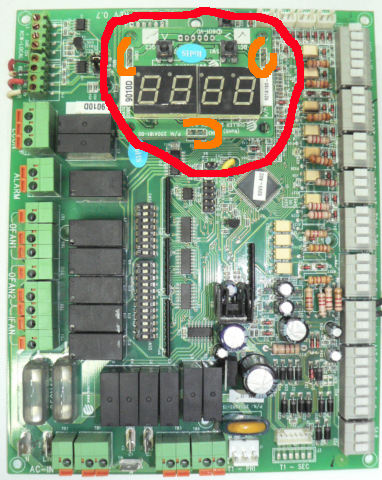
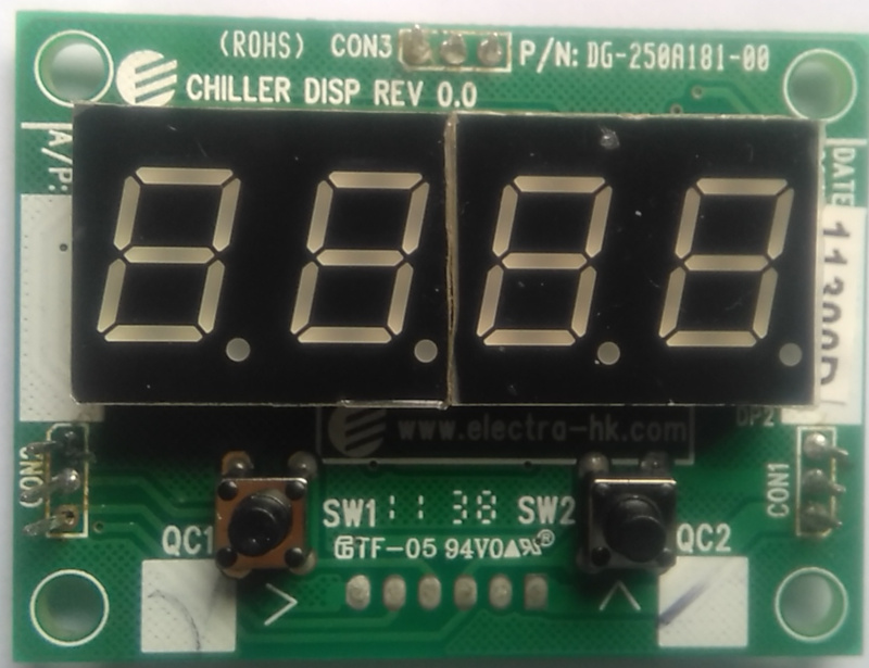
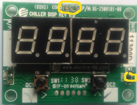
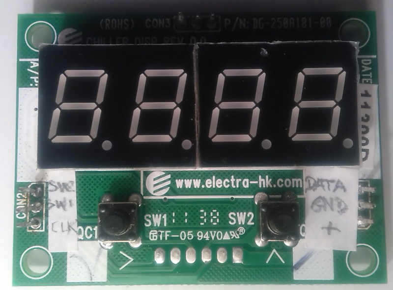
Par exemple, ici, le display provient d'une carte de climatiseur. Il y a 4 x 8 segments, avec 3 x 3 connecteurs bien visibles. Le 8ieme segment correspond au point après chaque chiffre. On ne voit pas les registres, mais il y en a très probablement puisqu'il n'y a que 7 connecteurs (hors masse et alimentation) pour 32 segments.
Reste à dessouder les 9 connecteurs, ou (plus rapide) les couper à la pince.
Etape n°2 - Trouver les registres à décalages
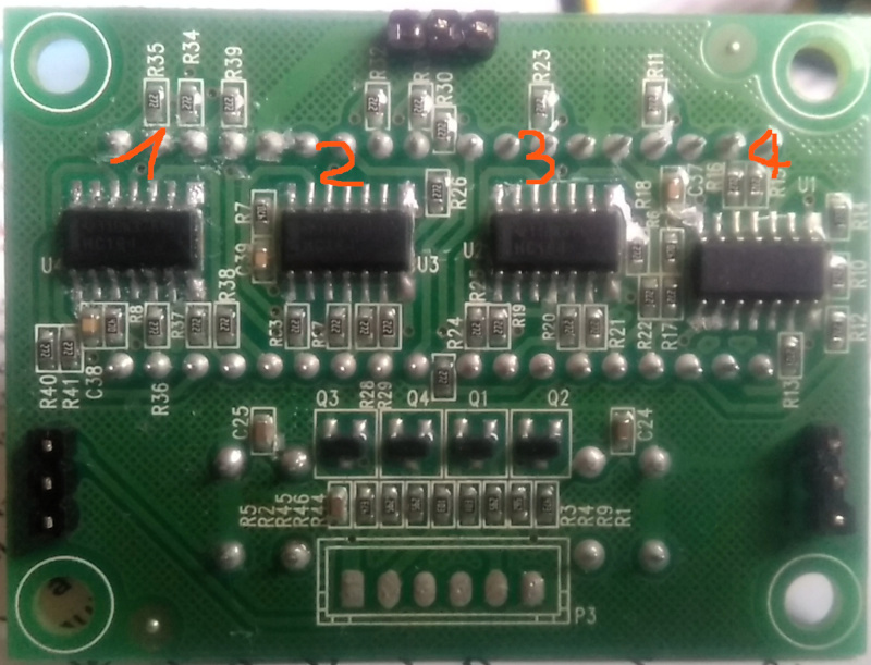
Il y a bien 4 chips derrière, qui correspondent à chacun des chiffres de l'afficheur. Après nettoyage et avec une bonne loupe, on arrive à lire "HC164". C'est une registre à décalage très courant et simple.
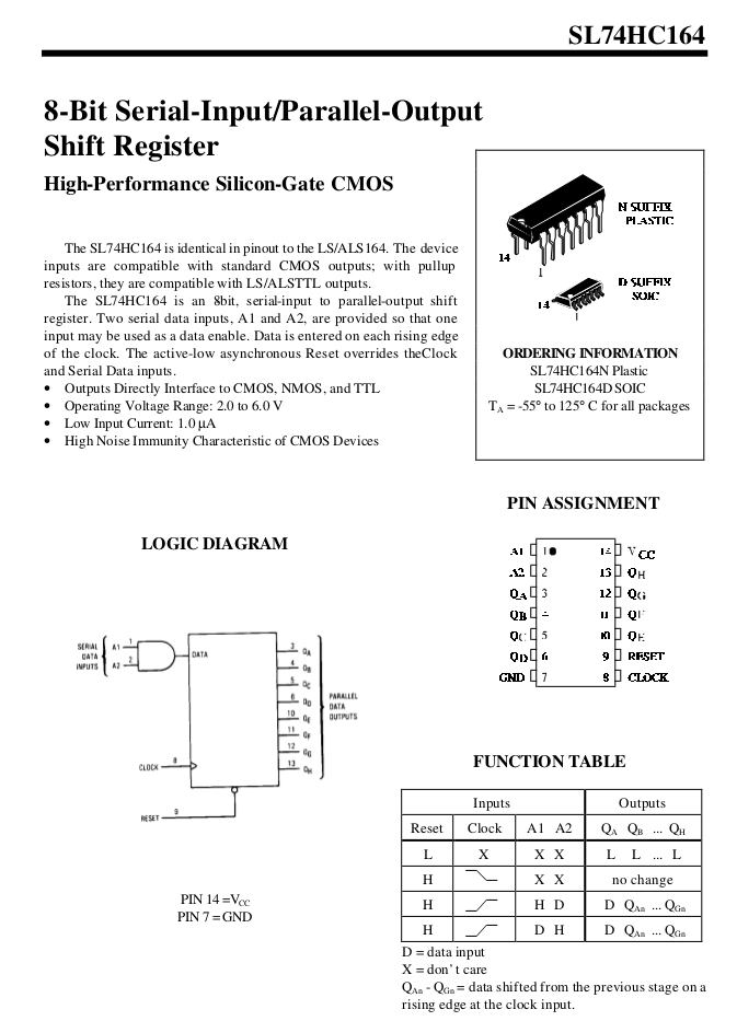
La doc est facile à trouver (voir ci-joint) et le principe simple:
- A chaque transition sur le pin CLK (Clock)
- La valeur en entrée DATA est "poussée" dans le registre et décale les 8 bits qui y étaient déjà.
- Le 8ieme bit est chainé sur l'entrée DATA du registre suivant
- Ainsi, après 8 x 4 = 32 transitions, tous les bits des 4 display sont valorisés.
Etape n°3 - Recherche de la masse
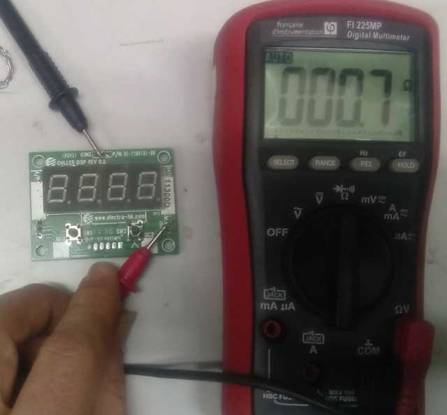
La carte est multi-couches, donc assez compliqué de s'y retrouver dans le circuit. En testant la connectivité entre les connecteurs, 4 connecteurs s'avèrent en lien direct (résistance nulle): les 3 du haut (CON3) et celui au centre à droite (CON1). Ceux-ci sont visiblement connectés sur le circuit à de grandes surfaces conductrices qui est très probablement la masse.
Etape n°4 - Recherche de l'alimentation +5V
Plus simple qu'il n'y parait: en général sur le circuit, le VCC est visualisé par une gravure "carrée". Justement, il y a un lien entre un carré sur le circuit et le connecteur le plus bas du CON1.
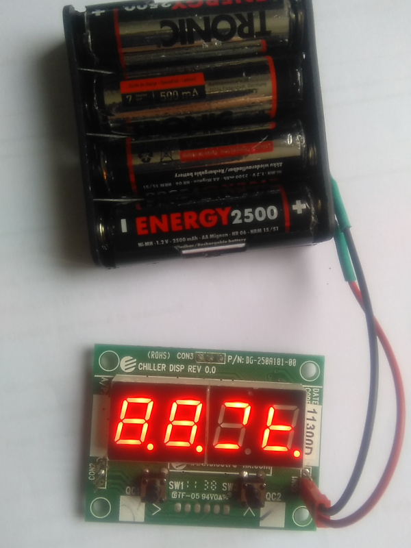
On peut alimenter ! Les LED vont s'afficher un peu au hasard au gré des mauvais contacts et parasites.
Victoire!
Etape n°5 - Recherche du Clk et Data
Plusieurs méthodes:
- Suivre les circuits CLK et DATA qui partent des HC164: L'idéal serait de pouvoir suivre les circuits visuellement, mais sur cette carte multi-couches c'est très difficile.
- Utiliser l'ohmètre pour trouver les liens avec les connecteurs: Pas de chance, aucun lien direct.
- Par élimination: On peut ignorer les 2 connecteurs du haut de CON 2: ceux-ci sont reliés aux interrupteurs sous le display.
Ainsi, il ne reste que 2 candidats: en haut du CON1 et en bas du CON2.
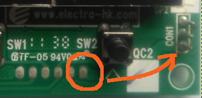
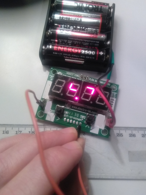
Avec un fil, connecter au + l'un des 2 pins. Le Data n'affiche rien. Mais le Clock fait avancer les segments de gauche à droite.
On a maintenant les 2 pins: voir la photo.
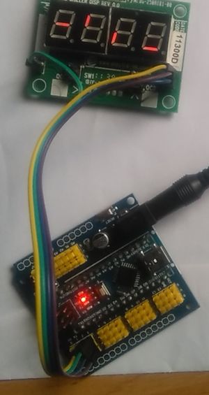
Etape n°6 - Connexion à l'Arduino
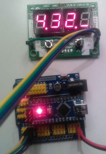
On peut connecter à l'Arduino, par exemple:
- GND -> GND
- CON+ -> VCC
- CLK -> Pin D3 (PWM)
- DATA -> Pin 2
Voici un exemple de code qui permet de contrôler totalement l'affichage.
Et voilà! Plus besoin de commander un nouvel afficheur au bout du monde...
Etape n°7 - Le Code
- define data 2
- define clock 3 //D PWM
- /*
- * CHILLER DISP Rev 0.0
- LED Display
- ___
- 6! 1 !2
- ! !
- ---
- ! 7 !
- 5! !3
- ---
- 8° 4 bits
- 12345678
- Connectors
- CON3
- GND GND GND
- SW2 DATA
- CON2 SW1 GND CON1
- CLK +5V
- */
- void setup()
- {
- pinMode(clock, OUTPUT); // make the clock pin an output
- pinMode(data , OUTPUT); // make the data pin an output
- }
- void loop() {
- // put your main code here, to run repeatedly
- shiftOut(data, clock, LSBFIRST, B00000000); // send this binary value to the shift register
- shiftOut(data, clock, LSBFIRST, B00000000); // send this binary value to the shift register
- shiftOut(data, clock, LSBFIRST, B00000000); // send this binary value to the shift register
- shiftOut(data, clock, LSBFIRST, B00000000); // send this binary value to the shift register
- delay(1000);
- shiftOut(data, clock, LSBFIRST, B00000001); // send this binary value to the shift register
- shiftOut(data, clock, LSBFIRST, B00000010); // send this binary value to the shift register
- shiftOut(data, clock, LSBFIRST, B00000100); // send this binary value to the shift register
- shiftOut(data, clock, LSBFIRST, B00001000); // send this binary value to the shift register
- delay(1000);
- shiftOut(data, clock, LSBFIRST, B00010000); // send this binary value to the shift register
- shiftOut(data, clock, LSBFIRST, B00100000); // send this binary value to the shift register
- shiftOut(data, clock, LSBFIRST, B01000000); // send this binary value to the shift register
- shiftOut(data, clock, LSBFIRST, B10000000); // send this binary value to the shift register
- delay(1000);
- shiftOut(data, clock, LSBFIRST, B00000000); // send this binary value to the shift register
- shiftOut(data, clock, LSBFIRST, B00000000); // send this binary value to the shift register
- shiftOut(data, clock, LSBFIRST, B00000000); // send this binary value to the shift register
- shiftOut(data, clock, LSBFIRST, B00000000); // send this binary value to the shift register
- delay(1000);
- shiftOut(data, clock, LSBFIRST, B10101010); // send this binary value to the shift register
- delay(1000);
- for(int i = 0; i < 4; ++i) //for 0 - 7 do
- {
- shiftOut(data, clock, LSBFIRST, B01010101); // bit shift a logic high (1) value by i
- delay(500); // delay 100ms or you would not be able to see it
- }
- delay(1000);
- }
